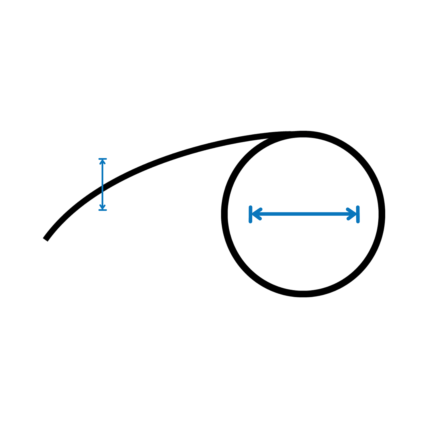
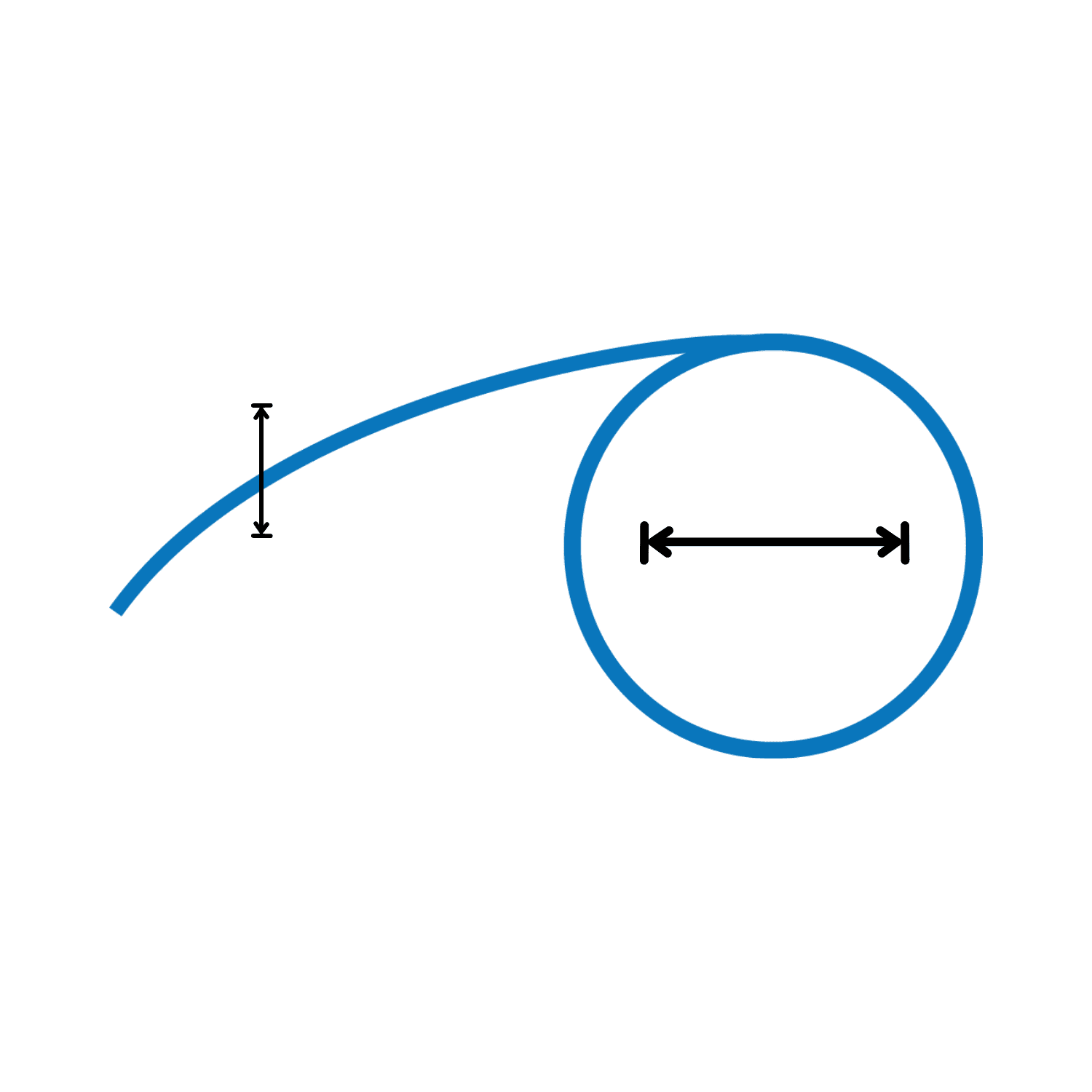
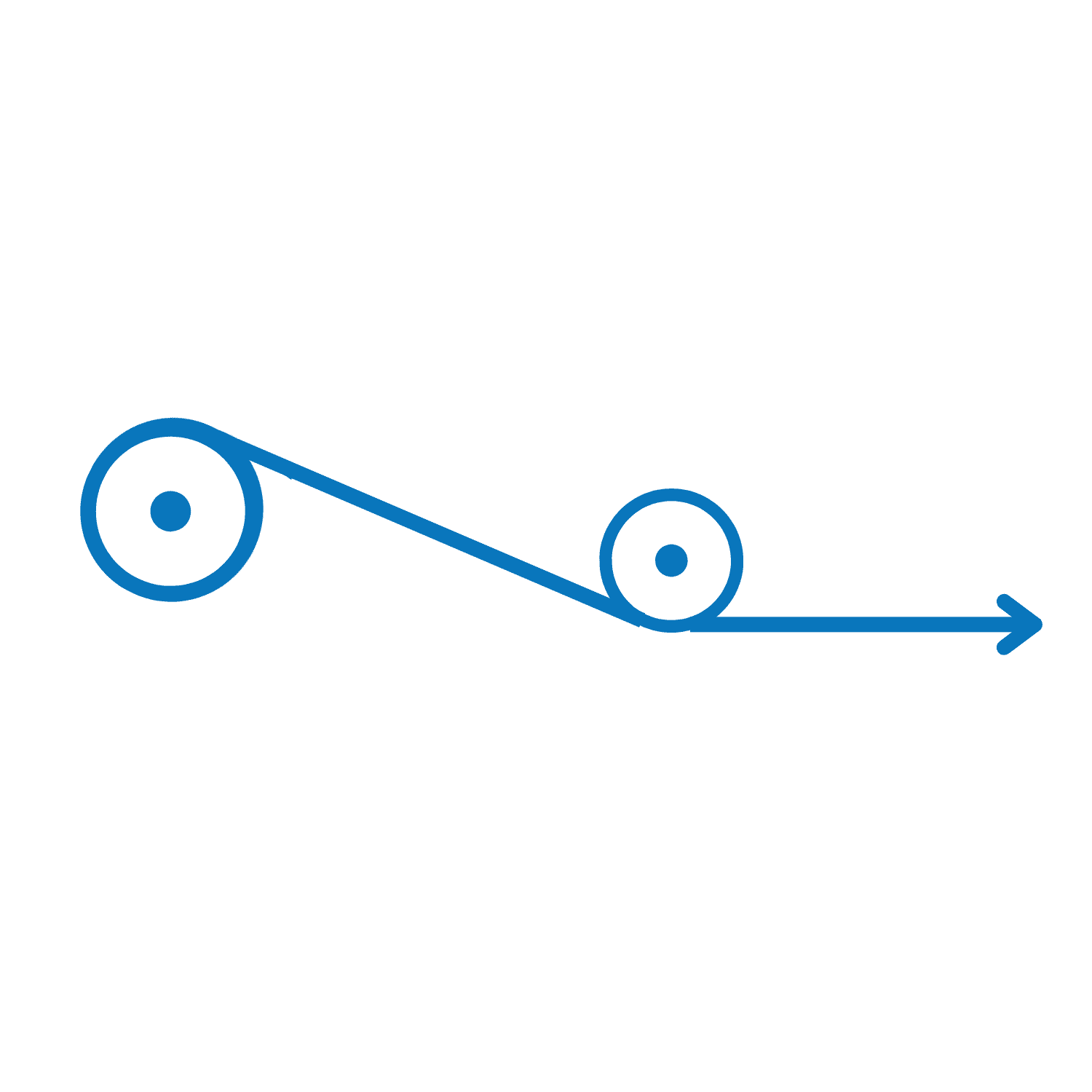
Constant Force Spring lined drawing showing width and diameter.

John Evans’ Sons is the leading international constant force spring manufacturer.  We take pride in our precision spring manufacturing and design.

Long deflection, without significant change of force, is a key characteristic of constant force springs. As a balancing mechanism, the spring is more compact and lighter than most other methods and can eliminate deadweights, linkages, cylinders, and other systems. As a return or retracting mechanism, it will provide a smooth, even, uniform load through its entire length of travel (deflection). Constant tensioning or pressure is also an attribute.

Many design factors will affect the time and cost needed to manufacture your constant force springs. Therefore, it’s important to work with a manufacturer like John Evans’ Sons that has the knowledge needed in the design phase.

Our strongest selling points are our custom design capabilities, in-house tooling services, precision manufacturing, a wide and varied stock spring selection, and our commitment to quality and on-time delivery.

Applications of Constant Force Springs

John Evans’ Sons’ constant force springs are in countless applications, including the Mars rovers Curiosity and Perseverance, to name a few. Constant force spring mechanisms apply constant force throughout their entire length, preventing them from uncoiling while in use. We design and manufacture standard and custom constant force springs for a broad range of applications, some of which include:

Surgical Devices
Aircraft Doors
Windows
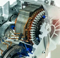
Electric Motors
Fire Dampers
Gym Equipment

Applications

Surgical Devices

Applications

Aircraft Doors

Applications

Windows

Applications

Electric Motors

Applications

Fire Dampers

Applications

Gym Equipment

Benefits Of Constant Force Springs

John Evans’ Sons’ constant force springs and assemblies can decrease your device cost and size by eliminating expensive, complex motors. Our constant tension springs provide:

Strong Force Yield Within Small Spaces
Mounts Easily to Existing Hardware
Smooth, Uniform Load Throughout the Entire Length of Travel (Deflection)
Extensive Linear Range
Compact Size

Constant Force Springs

A constant force spring provides a smooth, uniform load through its full length of travel. This type of spring comes in compact package sizes, offers extensive linear range, and yields strong force within confined spaces. It also easily mounts onto existing hardware.

Click to expand the graphic and see how the spring can interact with your products.

Linear Movement Mounting Full Extension & Spring Load Consult an Engineer
Close

Mounting

To mount a constant force spring, tightly wind it on a drum and attach the free end to the loading force. The diameter of the drum should be 10-20% larger than its inside diameter.

Close

Linear Movement

A tightly wrapped spring provides a smooth range of motion and constant linear force throughout its length of travel, or deflection. For this reason, constant force springs can easily fit either full or partial extension configurations and applications.

Close

Full Extension & Spring Load

Once the spring is extended to a length of 1.25x its diameter, it reaches its maximum load and can maintain this constant force regardless of how far it extends or retracts. The spring’s load only depends on the diameter of the spring and the width and thickness of the material.

Materials

The material selection for a constant force spring application is essential in determining the project and design costs. The best constant tension spring material varies depending on the type of environment it will be used in, such as corrosive and high-temperature environments, which can also affect the overall life of the spring and selected material.

The following materials are commonly used in the construction of the physical spring:

301 Stainless Steel

An austenitic chromium-nickel type of stainless steel that can be cold-worked to achieve high ductility and tensile strength. It does not harden by heat treatment, and although it is not magnetic in the annealed state, it does become magnetic with cold deformation.

Inconel

Inconel springs are ideal for use in corrosive environments exposed to salt water, aggressive air, or aggressive water conditions.

High Carbon Steel

Features significant hardness, due to more than 0.3% carbon content.

Mounting Methods

There are several mounting methods, and your application will determine which mounting method is best for your spring’s design. A constant force spring typically gets mounted by wrapping it tightly on a drum and then connecting the free end to the loading force. The relationship is also easily reversed.

The diameter of the drum should be larger than its inside diameter by 10% to 20%. Long extension applications may cause the strip to become unstable, requiring guidance to prevent recoil, kinking, or twisting. At maximum extension, one-and-a-half wraps should still be on the drum.

Idler pulleys need to have a larger diameter than the natural diameter and should not create back-bending against the curvature’s radius.

Performance Considerations

The life of a constant force spring is rated by the number of cycles it can perform before it begins to break, warp, or exhibit inconsistent constant return force. Springs are typically rated from 2,500 cycles to more than 1 million cycles.

The spring life varies and is dependent on the specific application as well as the following performance considerations:

Help meet specific force and durability requirements within the spatial constraints. A thicker material with a smaller coil diameter could provide a higher force, but it might also wear out faster, whereas a thinner material with a larger diameter could last longer but deliver less force.

Maximizes force output, enhances durability, and ensures long-term reliability under various environmental conditions.

Crucial in preparing constant force springs for specific applications, especially in industries requiring precision and safety due to the handling and exposure of the strip edges. Optimizes the performance, durability, and safety of the spring.

Understanding the specific chemical environment and selecting materials and coatings accordingly are critical steps in ensuring the reliable performance and longevity of constant force springs in chemically aggressive environments.

Depending on the temperature conditions a spring will face selecting the appropriate material and design features is vital. Ensuring the spring performs reliably across the intended temperature range.

Significantly affect the performance of constant force springs by introducing dynamic forces, vibration, wear, and potential heat-related issues.

Affects everything from force consistency and resistance to environmental factors to the spring’s ability to withstand mechanical stresses and maintain its integrity over time.

Can negatively affect the performance of constant force springs by causing force inconsistencies, misalignment, increased wear, reduced load capacity, and operational noise.

Improves the performance and longevity by reducing friction, wear, and other negative factors.

Product Resources

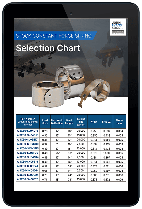
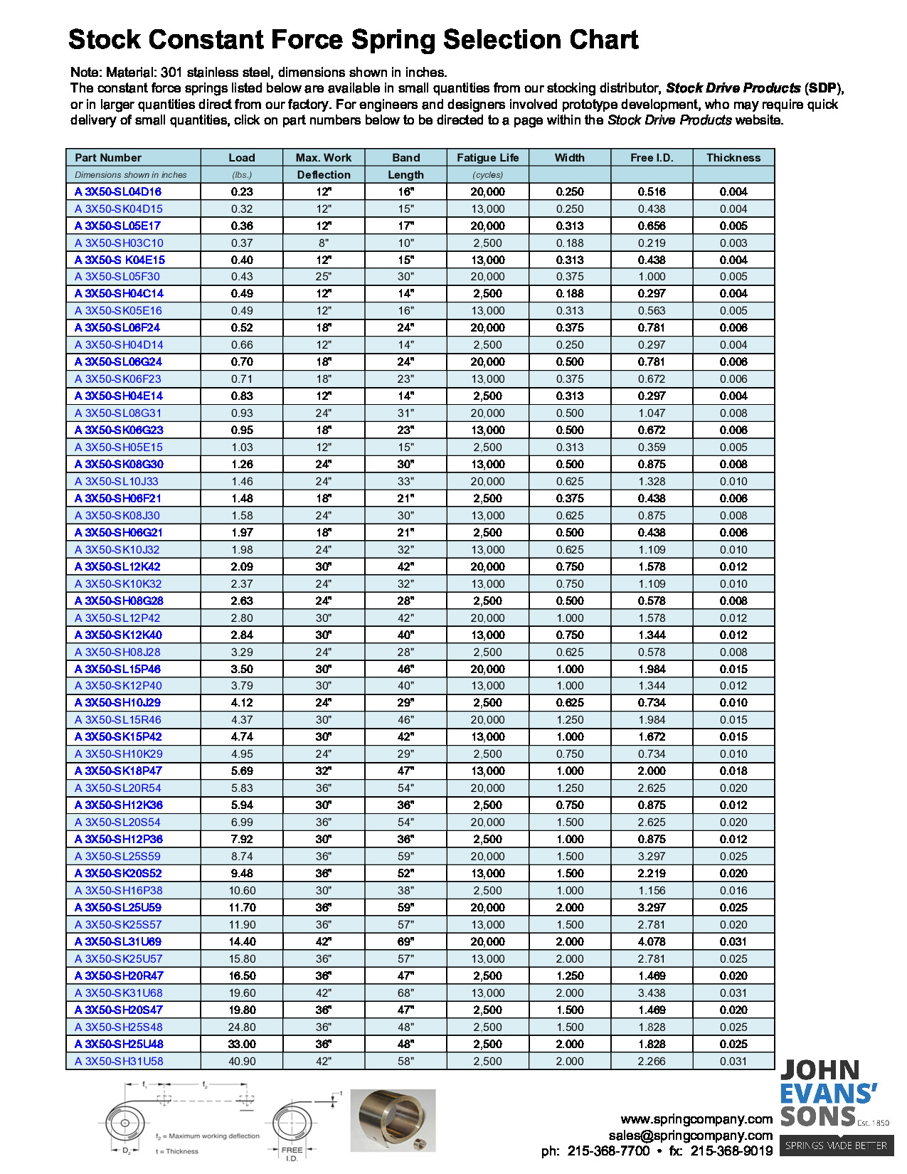
Stock Constant Force Spring Selection Chart

Stock Constant Force Spring Selection Chart

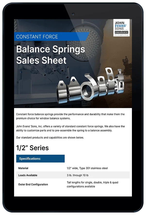
Constant Force Balance Springs Sales Sheet

Constant Force Balance Springs Sales Sheet

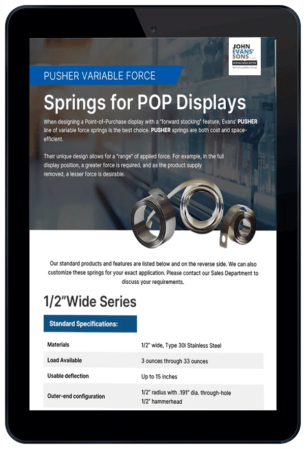
Pusher Variable Force Springs for POP Displays

Pusher Variable Force Springs for POP Displays

Constant Force Spring Design Considerations

There are many design factors that will affect the time and cost needed to manufacture your spring. Therefore, it’s important to work with a manufacturer like John Evans’ Sons that has the knowledge required for the design phase.

  • Mounting Methods: There are several mounting methods. Your application will determine which mounting method is best for your spring’s design.
  • Material: The material selection is an important component of the design and project cost. The optimal spring material is often different in high-temperature and corrosive environments. Material will certainly affect the design and project cost. High temperatures or corrosive environments will also affect the life of a spring and the required material.
  • Diameter and Load: Length, material width, thickness, and coil diameter affect the spring’s load. Increased loads can be obtained by using two or more constant force springs interwound, in tandem, or in other configurations.

All of these, plus other technical considerations, need to be discussed and specified prior to creating prototypes. Our design engineering team can help ensure calculations and configurations are exact in the design phase.

Our springs are most often used in the following industries and applications:

Not sure if constant force springs can provide the right action for your product? Contact John Evans’ Sons for more information.

Constant Force Spring line drawing showing width and diameter.

Spring Comparison Chart
for design parameter comparison (matl. thickness vs. cycle life vs. coiled dia.)

(material: T301 SS, Calculations shown are at 1.0” width, interpolate for other spring material widths)

Material Thickness2,500 cycles
10,000 cycles20,000 cycles75,000 cycles150,000 cycles
Coiled Dia.Load (lbs.)Coiled Dia.Load (lbs.)Coiled Dia.Load (lbs.)Coiled Dia.Load (lbs.)Coiled Dia.Load (lbs.)
0.0020.151.30.1710.220.650.330.320.440.17
0.0030.2220.251.50.3210.480.50.660.26
0.0040.32.60.3420.441.30.650.650.890.35
0.0050.363.30.432.50.551.60.810.81.110.44
0.0060.4440.5130.6520.9511.330.52
0.0080.595.20.6940.872.61.281.31.780.7
0.010.736.60.8651.083.31.591.62.220.87
0.0120.8781.0361.341.9122.671.04
0.0141.029.31.271.524.62.222.33.071.2
0.0161.1610.61.3781.735.32.532.73.61.4
0.0181.3111.91.5491.965.92.85341.56
0.021.4613.21.71102.186.63.23.34.441.74
0.0221.6114.51.89112.377.23.483.64.891.91
0.0251.8116.52.1412.52.728.244.15.552.18
0.0282.0418.52.4143.049.54.484.66.232.44
0.0322.2620.52.65 15.53.3610.24.945.16.92.7
Constant force spring variables & formula.

Selection Charts for the Ideal Constant Force Spring

Selection Charts for the Ideal Constant Force Spring

Part NumberLoadMax Work DeflectionBand LengthFatigue Life (cycles)WidthFree I. D.Thickness
A 3X50-SL04D160.2312"16"20,0000.25"0.5160.004
A 3X50-SK04D15 0.3212"15"13,0000.25"0.4380.004
A 3X50-SL05E17 0.3612"17"20,0000.3125"0.6560.005
A 3X50-SH03C10 0.378"10"2,5000.1875"0.2190.003
A 3X50-SK04E15 0.412"15"13,0000.3125"0.4380.004
A 3X50-SL05F30 0.4325"30"20,0000.375"1.00.005
A 3X50-SH04C14 0.4912"14"2,5000.1875"0.2970.004
A 3X50-SK05E16 0.4912"16"13,0000.3125"0.5630.005
A 3X50-SL06F24 0.5218"24"20,0000.375"0.7810.006
A 3X50-SH04D14 0.6612"14"2,5000.25"0.2970.004
A 3X50-SL06G24 0.718"24"20,0000.5"0.7810.006
A 3X50-SK06F23 0.7118"23"13,0000.375"0.6720.006
A 3X50-SH04E14 0.8312"14"2,5000.3125"0.2970.004
A 3X50-SL08G31 0.9324"31"20,0000.5"1.0470.008
A 3X50-SK06G23 0.9518"23"13,0000.5"0.6720.006
A 3X50-SH05E15 1.0312"15"2,5000.3125"0.3590.005
A 3X50-SK08G30 1.2624"30"13,0000.5"0.8750.008
A 3X50-SL10J33 1.4624"33"20,0000.625"1.3280.010
A 3X50-SH06F21 1.4818"21"2,5000.375"0.4380.006
A 3X50-SK08J30 1.5824"30"13,0000.625"0.8750.008
A 3X50-SH06G21 1.9718"21"2,5000.5"0.4380.006
A 3X50-SK10J32 1.9824"32"13,0000.625"1.1090.010
A 3X50-SL12K42 2.0930"42"20,0000.75"1.5780.012
A 3X50-SK10K32 2.3724"32"13,0000.75"
1.1090.010
A 3X50-SH08G28 2.6324"28"2,5000.5"
0.5780.008
A 3X50-SL12P42 2.830"42"20,0001"1.5780.012
A 3X50-SK12K40 2.8430"40"13,0000.75"1.3440.012
A 3X50-SH08J28 3.2924"28"2,5000.625"0.5780.008
A 3X50-SL15P46 3.530"46"20,0001"1.9840.015
A 3X50-SK12P40 3.7930"40"13,0001"1.3440.012
A 3X50-SH10J29 4.1224"29"2,5000.625"0.7340.010
A 3X50-SL15R46 4.3730"46"20,0001.25"1.9840.015
A 3X50-SK15P42 4.7430"42"13,0001.0"1.6720.015
A 3X50-SH10K29 4.9524"29"2,5000.75" 0.7340.010
A 3X50-SK18P47 5.6932"47"13,0001.0"2.00.018
A 3X50-SL20R54 5.8336"54"20,0001.25"2.6250.020
A 3X50-SH12K36 5.9430"36"2,5000.75"0.8750.012
A 3X50-SL20S54 6.9936"54"20,0001.5"2.6250.020
A 3X50-SH12P36 7.9230"36"2,5001.0"0.8750.012
A 3X50-SL25S59 8.7436"59"20,0001.5"3.2970.025
A 3X50-SK20S52 9.4836"52"13,0001.5"2.2190.020
A 3X50-SH16P38 10.630"38"2,5001.0"1.1560.016
A 3X50-SL25U59 11.736"59"20,0002.0"3.2970.025
A 3X50-SK25S57 11.936"57"13,0001.5"2.7810.020
A 3X50-SL31U69 14.442"69"20,000
2.0"4.0780.031
A 3X50-SK25U57 15.836"57"13,0002.0"2.7810.025
A 3X50-SH20R47 16.536"47"2,5001.25"1.4690.020
A 3X50-SK31U68 19.642"68"13,0002.0"3.4380.031
A 3X50-SH20S47 19.836"47"2,5001.5"1.4690.020
A 3X50-SH25S48 24.836"48"2,5001.5"1.8280.025
A 3X50-SH25U48 3336"48"2,5002.0"1.8280.025
A 3X50-SH31U58 40.942"58"2,5002.0"2.2660.031

Available from our distributor, Stock Drive Products. Tel: 516-328-3300

Constant Force Spring Technical Information and Diameter vs. Load Chart (matl: T301 SS, calculations shown are at 1.0" width, interpolate for other spring material widths)

2,500 cycles10,000 cycles20,000 cycles75,000 cycles150,000 cycles
Material ThicknessCoiled Dia.LoadCoiled Dia.LoadCoiled Dia.LoadCoiled Dia.LoadCoiled Dia.Load
0.002
0.151.30.171.0 0.220.650.330.320.440.17

0.003
0.222.00.251.50.321.00.480.500.660.26
0.0040.302.60.341.50.441.30.650.650.890.35
0.0050.363.30.432.50.551.60.81 0.801.110.44
0.0060.444.00.51 3.00.652.00.951.001.330.52
0.0080.595.2 0.694.00.872.61.28 1.301.780.70
0.0100.736.60.865.01.083.31.591.602.220.87
0.0120.878.01.036.01.304.01.912.002.67 1.04
0.0141.029.31.207.01.524.62.222.303.071.20
0.0161.1610.61.37 8.01.735.32.532.703.601.40
0.0181.3111.91.549.01.965.92.853.004.001.56
0.0201.4613.21.71 10.02.18 6.63.203.304.441.74
0.0221.6114.5 1.8911.02.377.23.483.604.891.91
0.0251.8116.52.1412.52.728.24.004.10 5.552.18
0.0282.0418.52.4014.03.049.54.484.606.232.44
0.031 2.2620.5 2.6515.53.3610.24.945.106.902.70
STOCK Constant Force Spring Selection Chart

Order small quantities

Two Constant Force Springs. John Evans’ Sons is an international leader in constant force spring design and manufacturing.
Constant Force Springs. John Evans’ Sons is an international leader in constant force spring design and manufacturing.
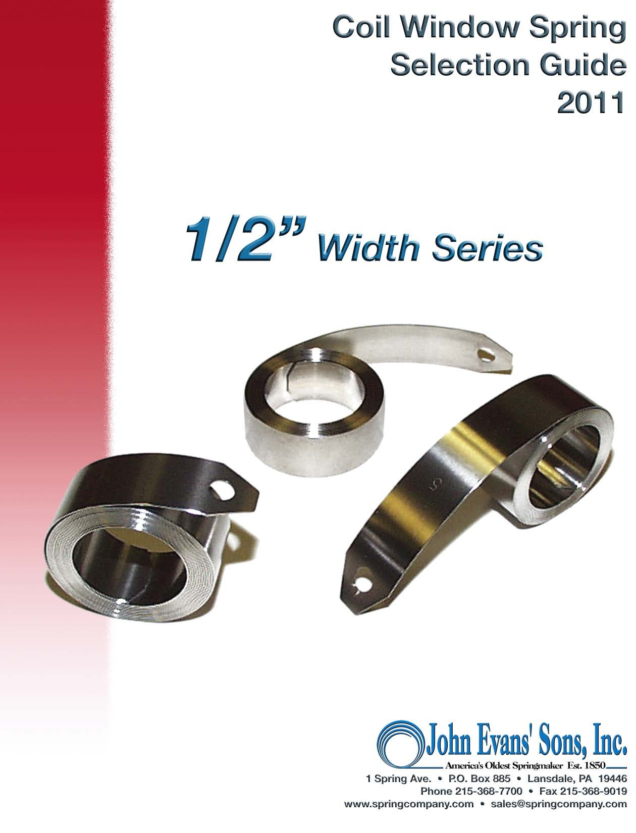
Window Balance Springs Download .pdf
Window Balance Springs

1/2″ Constant Force Window Balance Selection Guide

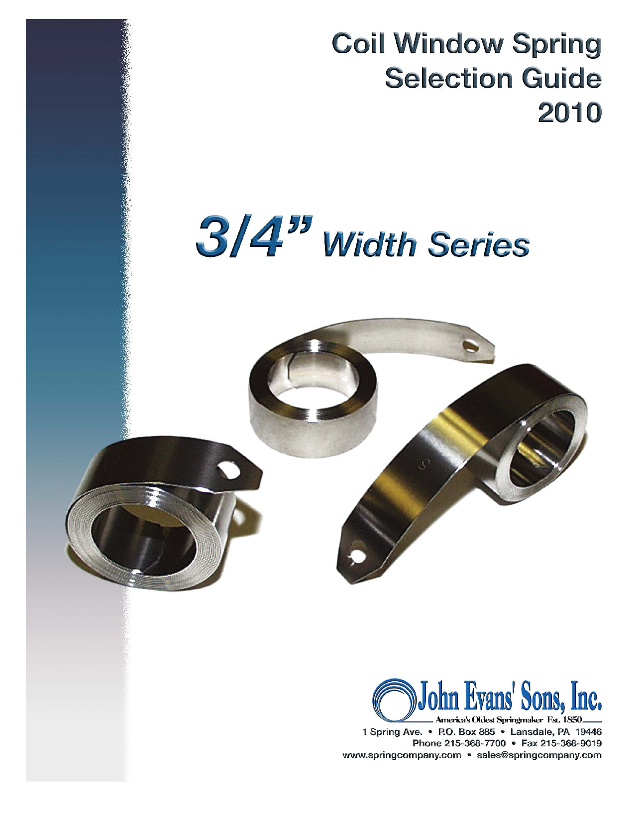
Window Balance Springs Download .pdf
Window Balance Springs

3/4″ Constant Force Window Balance Selection Guide

Contact John Evans’ Sons to Learn More About Constant Force Springs

The technical team at John Evans’ Sons provides in-depth knowledge and expertise, assisting customers with each phase of the manufacturing process. We are ready to answer questions and can help customers define the product they need to meet the demands of a specific application. We produce standard and custom constant force springs, and we are ready to work with you on any of your customization needs.

Contact us to learn more about our products, or request a quote for assistance with your next project.

Request Your Custom Constant Force Spring Design

"*" indicates required fields

1Step 1: Personal Information
2Step 2: Specifications and Dimensions

Submit your constant force spring requirements below and a member of our team will be in touch. If you do not have any particular requirements for certain specs listed, kindly leave those fields empty.
Personal Information